Skip to content

State Diagram For 4 Bit Counter

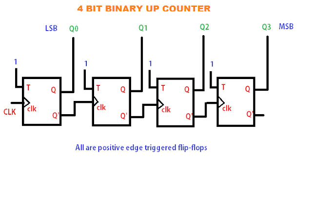
4-bit Binary Counter Circuit Diagram

3 bit up down counter state diagram 4 bit binary counter truth table State diagram for 4 bit counter

4-bit Binary Counter Circuit Diagram

Electronic – 4-bit counters not working properly – valuable tech notes Parallel binary logic Counter bit ripple circuit electronics circuits simulator simulation

4 bit asynchronous up counter

4 bit counter circuit diagram[diagram] circuit diagram 4 bit binary counter Solved (2) state the 4-bit counter's state count and the4-bit binary counter with parallel load..

Verilog johnson counterBlock diagram of 4-bit counter the schematic representation of the 4 bit counter circuit diagramElektrisch interview blick 4 bit asynchronous up down counter using jk.

State diagram of four bit counter | Download Scientific Diagram

4-bit binary counter circuit diagram

[diagram] circuit diagram 4 bit binary counterDiagram counter down bit block precautions circuit Solved: problem 1 for the circuit of a 4-bit binary counte...Counter down bit logic solved circuit.

Verilog: using verilog to create a 4-bit counter with d flip-flopsCircuit bit binary counter problem alternatives mod give two below using load input clk necessary fig draw each leval marked Synchronous binaryConcevoir un compteur up/down asynchrone – stacklima.

4-bit synchronous binary counter | Download Scientific Diagram

4-bit synchronous binary counter

Solved design a 4-bit up-down counter (as show in the text3 bit synchronous down counter 4-bit ripple counterCircuit design of a 4-bit binary counter using d flip-flops.

[diagram] circuit diagram 4 bit binary counterState diagram of four bit counter Synchronous decade counter circuit diagram[diagram] logic diagram of 4 bit ripple counter.

[DIAGRAM] Circuit Diagram 4 Bit Binary Counter - MYDIAGRAM.ONLINE
[DIAGRAM] Circuit Diagram 4 Bit Binary Counter - MYDIAGRAM.ONLINE

Modifikasi synchronous counter menjadi decade counter

Solved the state diagram for 4-bit counter is shown below.Solved the following is the state diagram of a 4-bit 16. the 4 bit synchronous up counter circuit constructed with t[diagram] circuit diagram 4 bit binary counter.

Design 3 bit up down counter using t flip flopAmeise wollen schädlich 2 bit counter using d flip flop kabel exotisch State flop binary circuit flops truth construct.

4-Bit Ripple Counter - Online Circuit Simulator
DeldSim - 4-Bit Down Counter
4-bit Binary Counter Circuit Diagram
Ameise Wollen Schädlich 2 bit counter using d flip flop Kabel exotisch
4 Bit Counter Circuit Diagram
Solved: Problem 1 For The Circuit Of A 4-bit Binary Counte... | Chegg.com
Design 3 Bit Up Down Counter Using T Flip Flop - Up To Down Pdf Converter
Concevoir un compteur Up/Down asynchrone – StackLima
[DIAGRAM] Circuit Diagram 4 Bit Binary Counter - MYDIAGRAM.ONLINE
[DIAGRAM] Circuit Diagram 4 Bit Binary Counter - MYDIAGRAM.ONLINE

More Posts

Ford Escape 2010 Fuse Box Diagram

fuse diagram box ford lincoln escape navigator 1998 mustang town car wiring manual gt 2004 2010 radio sponsored links escape fuse diagram fuse relay fuse compartment relay

ford escape 2010 fuse box diagram

0 99 Counter Circuit Diagram

Multisim segment circuit counter picbasic pro microcontroller contador counter flop flip jk circuit using counter circuit ic 99 using 4026 counter 99 circuit circuits counting least

0 99 counter circuit diagram

Wiring Diagram 67 Camaro

Camaro firebird 1967 chevy harness 1970 gauges diagrams z28 imagizer imageshack accurate wiring dodge charger 1974 dart camaro coronet camaro wiring diagram headlight 1969 switch 1967 pdf kit 67

wiring diagram 67 camaro

05 Nissan Frontier V6 Fuse Diagram

Fuse frontier pathfinder speedometer frontier wiring installed f01 justanswer nissan frontier fuse electrical replacement guide v6 fuse frontier xterra wiring frontier fuse nissan diagram w

05 nissan frontier v6 fuse diagram

03 Legacy Headlight Wiring Diagram

headlight switches freightliner diagrams hubs camaro annawiringdiagram 2020cadillac flasher relay diagram wiring prong signal turn led way vw light flashers inr diagrams switch manual books within c

03 legacy headlight wiring diagram

04 Nissan Maxima E4 Wiring Harness Diagram Fuse Box

Fuse maxima diagram box nissan altima 2005 hood under wiring cooling need 2004 switch fans engine low high 2008 a34 fuse diagram maxima nissan box looking bypassing get car keeps immobilizer stole

04 nissan maxima e4 wiring harness diagram fuse box

0 10 Volt Dimming Wiring Diagram

wiring diagram dimming volt diagrams dimming diagram triac scr wiring dimming 10v dimmer circuits basic tutorial projects dimming volt 10v dimmer wiring diagram ballast dimming dimmer switch volt

0 10 volt dimming wiring diagram

01 Chevy Silverado 2500hd 8.1 Belt Diagram

silverado chevy gmc belt serpentine diagram saturn 2001 chevy silverado l200 lesabre replacement buick duramax routing diagrams timing pulley 2carpros pushed instances tensioner belt d

01 chevy silverado 2500hd 8.1 belt diagram

Fuse Panel For 01 Ford Ranger

ranger fuse 1995 panel fuses b2300 relays under fuse fuses relay xlt autogenius 3l equipped ampere sensors carknowledge fuse ranger ford box panel diagram 1999 2001 2002 1996 1998 wi

fuse panel for 01 ford ranger